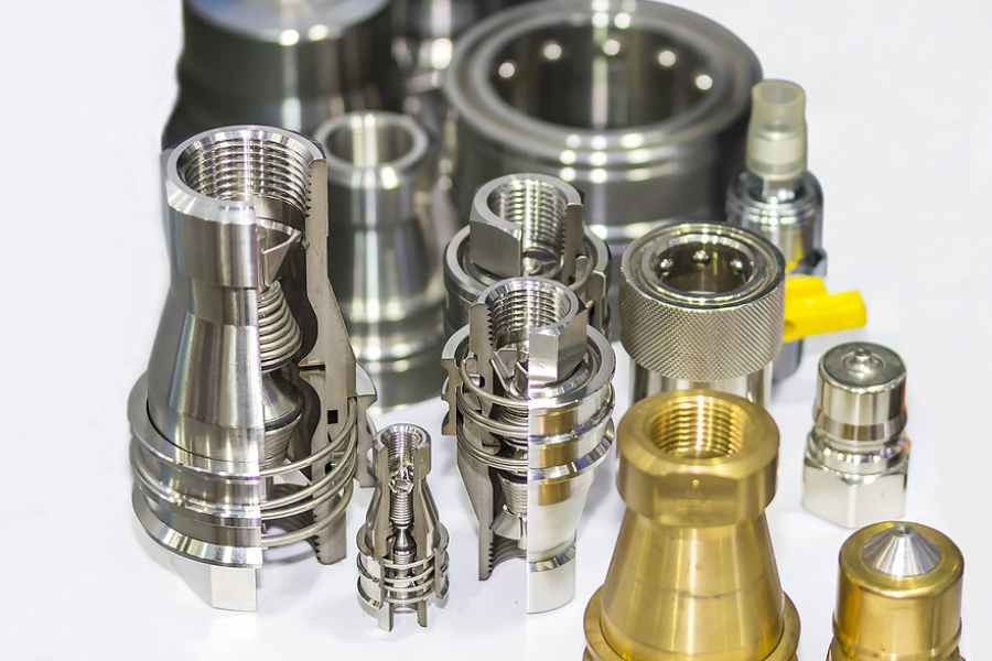
Dry Disconnect Coupling Selection Guide: What To Look For
Dry disconnect couplings are engineered to establish and safely sever connections in gas or fluid transfer systems, which is especially vital when handling hazardous, valuable, or hard-to-clean substances. Their innovative self-sealing mechanisms ensure secure, spill-free operations, protecting both personnel and materials. When selecting a suitable coupling, here are the key considerations to look for:
1. Locking/coupling mechanisms
- Ball-lock (ball-latching)
Uses spring-loaded balls around the socket body that snap into a groove on the plug when a sleeve is released. Pulling back on the sleeve frees the balls to move outward, allowing disconnect. Ball-lock couplings are very common and versatile, enabling rapid one-handed connection and disconnection. They handle moderate pressures (typically up to a few hundred psi) and are valued for ease of use. Over time, repeated use can wear the balls or sleeve seal, so quality and inspection matter to prevent leaks.
- Cam-lock (cam-and-groove)
Employs two hinged levers on the female half. The plug is inserted, and the levers are flipped down (cammed) to clamp the halves together. Cam-lock couplers are robust and widely used for larger hoses (often in bulk liquid transfer) because they can handle heavy loads. However, they are bulkier and generally slower to operate (requiring two hands to open both arms). The cam arms can wear or loosen if couplings are mated and unmated very frequently, which can eventually allow leakage. They require more clearance than smaller couplers.
- Roller-lock
Contains one or more spring-loaded rollers or pins in the socket ID. As the tapered plug is inserted, ramps on the plug push these rollers outward. Once fully seated, the rollers snap into a retaining groove on the plug’s body. This creates a strong positive lock. Roller-lock couplings tend to endure high pressure and are rugged but may be slightly slower or heavier than ball-lock types. The push-pull connection is secure, but alignment must be correct, and the mechanism is relatively complex.
- Pin-lock (push-lock)
Features pins in the socket that are forced back by a ramp on the plug during insertion. When the plug is fully inserted, spring-loaded pins snap into a groove, locking the halves without requiring sleeve retraction. This design allows true push-to-connect operation (one-handed use), making it very quick and easy to engage. Pin-lock couplings are often used on smaller pneumatic lines for fast tool changes. They are not typically rated for the highest pressures; users should confirm that the coupling’s pressure rating matches the application.
- Bayonet
Uses matching lugs and grooves on the plug and socket. The plug is inserted and then given a partial twist (often about 1/4 turn) so the lugs ride under a retention lip on the socket. Bayonet couplers provide a very sturdy connection with minimal disconnection force. They are rated for very high pressures (some designs handle up to ~3,000 psi) and can be disconnected one-handed by twisting. The drawback is that bayonet couplings require alignment and a twisting motion, so they are somewhat slower to connect than ball or pin types. However, their simple construction and heavy-duty performance make them suitable for critical or high-pressure applications.
Each mechanism has trade-offs in speed, ease, safety, and durability. Ball-lock and pin-lock types are the fastest and simplest to operate, while cam-lock and bayonet types handle larger flows or higher pressure with a more secure (but slower) connection. Always match the mechanism to the use case (e.g. one-handed push vs heavy-duty locking).
2. Shut-off configuration types
- Full flow (no shut-off)
Full flow couplings have no internal valves; they provide a straight-through flow path. This maximises flow and minimises pressure drop, but neither half seals when disconnected. Fluid is fully exposed on both sides of the break, so this is only advisable for non-hazardous gases or fluids or where an upstream valve is used. These “straight-through” couplers are often chosen purely for high flow and simplicity. Before disconnecting, the line must be manually shut off upstream to avoid spills or “hose whip.” Because there are no valves, the fluid in the disconnected hose or equipment will drain freely, which can be unsafe if misapplied.
- Single shut-off
One side (usually the female half) has a built-in poppet or valve that closes when the halves separate. After disconnection, fluid flow is stopped on one side, but the other side (the plug end) remains open to the line. This means a slight amount of fluid (or pressure) may vent from the non-valved side when disconnecting. Single-shutoff couplers are useful for situations like pressure-filling a vessel: you fill, then disconnect, and the vessel (or supply) stays isolated. They are simpler and cheaper than double valves, but operators must beware: a pressurised feed line may “blow off” when connecting if the valve has not been sealed properly, so eye protection and careful procedure are advised.
- Double shut-off
Both halves contain valves that close on disconnection. After disconnecting, flow is blocked on the supply side and the receiving side. Thus, each disconnected line is individually sealed under pressure. This configuration prevents loss of liquid or gas from either side and keeps system parts pressurised. Double-shutoff (often called “dry-break”) couplers are ideal for hazardous, expensive or toxic fluids. They substantially reduce spills and vapour emissions.
In practice, some residual fluid or pressure may linger in the mating halves, so it’s good practice to depressurise carefully, but the double valves keep fresh fluid from running out. For even stricter containment, “dry-break” couplings ensure the valves close before any seal breaks and the faces mate flush, virtually eliminating even drips. In summary, full-flow couplers favour throughput, single-shutoff favours simplicity, and double-shutoff maximises containment and safety.
3. Pressure rating and size (flow) considerations
Always select a coupling rated for the system’s pressure. Coupling pressure ratings specify the maximum continuous (nominal) working pressure. It’s wise to choose a coupling with a rating well above your operating pressure to allow for pressure spikes or transient surges. Many manufacturers provide tables or Cv (flow-coefficient) data showing pressure drops at various flows. Check these to ensure your flow rate won’t exceed the coupling’s capacity. If in doubt, over‐specify the pressure rating and regularly inspect couplings for wear. Remember also that gases behave differently (compressibility) than liquids; check that the coupling’s rating applies to your fluid type at your operating temperature.
When it comes to flow size, the coupling’s internal bore or effective orifice determines the flow capacity. A small-diameter coupling can significantly restrict flow and cause a pressure drop (and energy loss) in the system. As such, make sure to match the coupling size to the hose or piping ID to avoid bottlenecks. For high-flow or viscous fluids, use a larger coupling or one designed for full flow. As a rule, oversizing the coupling slightly can reduce pressure drop; however, the coupling must still fit the hose and fittings. Conversely, an undersized coupling will throttle flow and may cause excessive backpressure or heat. Always review the coupling’s Cv (flow coefficient) or pressure-drop curves for the expected flow rate.
4. Sealing mechanisms
- O‑ring seals
The most common sealing method uses elastomeric O-rings that press between the two faces or around an internal poppet. These provide a tight seal when the coupling is assembled. Standard materials include nitrile (Buna-N), EPDM, fluorocarbon (Viton), silicone or PTFE, chosen for compatibility with the fluid’s chemistry and temperature. O‑ring seals are simple and reliable, but their effectiveness depends on material selection and maintenance. High temperature, aggressive chemicals or particulates can degrade an O‑ring. Routine inspection of the O-rings (and replacing hardened or damaged seals) is a key maintenance practice to prevent leakage. Because O-rings are elastomeric, even a perfect seal has a very tiny leakage rate (often measured in standard cm³/s) – so “zero leak” is theoretical, but modern designs minimise this.
- Piston-cylinder (poppet) seals
Some couplings use a piston or poppet valve in each half. When disconnected, springs push the pistons closed against seats. Upon connecting, the pistons retract to open flow. Because the pistons form metal-to-metal or pre-loaded ring seals, a well-designed piston seal can eliminate dripping on disconnect. In these designs, fluid loss on break-away is practically zero, as the valves snap shut automatically. Piston-seal couplings are favoured when any fluid escape is unacceptable. However, they can be more complex internally and may incur a small pressure drop when open.
- Front (flat-face) seals
Many dry-break couplings have flat mating faces with seals mounted directly on the face (often a toroidal O-ring in a recess). When uncoupled, the faces are flush, exposing only the thin seal ring. Upon connection, these seals contact before the fluid path opens, wiping away debris and minimising exposure. This front-seal approach is generally robust for a wide range of fluids. Because the seals are at the front, air ingression and spills are minimised when connecting/disconnecting. Flat-face couplings often combine piston-style valves with a flush face. In essence, this method is another form of piston/poppet design but emphasises a “no dead leg” face.
5. Design and ergonomic improvements
Modern dry couplers increasingly incorporate user-friendly and safety-enhancing features. Many use ergonomic handles and levers to reduce operator strain. For instance, some designs offer a single-action lever or paddle that opens both valves in one motion. Others provide contoured grip surfaces (twin square or round handles) to improve hand traction in gloves or harsh weather. Such improvements speed up coupling operations and lower the chance of hand injuries.
Manufacturers also add safety interlocks. A common feature is a lock pin or latch that prevents the coupling from opening unless intentionally released. This is crucial in situations with vibration or accidental tugs: the pin stops the arms or sleeves from inadvertently opening. For example, a “lock pin” in some designs catches on the arm until manually disengaged, effectively making accidental drops or bumps harmless.
Conclusion
Selecting the right dry disconnect coupling is all about matching specifications and ensuring clean, safe, and efficient fluid handling tailored to your operational needs. Understanding the various features discussed above allows organisations to be better equipped to make a choice that reduces downtime, improves worker safety, and supports long-term reliability. Whether you’re outfitting a new system or upgrading an existing one, a well-informed selection pays off in performance and peace of mind.
Looking for safe, reliable fluid transfer solutions? Pharmchem supplies premium dry disconnect couplings designed to meet rigorous industry standards. Reach out to our team to ensure your operations run cleanly, safely, and efficiently with the right fittings from the start.